
Global use of spinal cord stimulation for treatment of pain is increasing steadily—it is expected that the global market for spinal cord stimulation devices would be around $2 billion USD in 2024.
Technological advances in magnetic resonance imaging (MRI) means that practice guidelines state MRI as gold standard for thorough clinical evaluation and diagnosis of numerous disorders of the central nervous system, musculoskeletal system and cardiovascular system. Inability to undergo MRI safely clinically disadvantages patients with implanted neurostimulator devices.
The Royal College of Radiologists has predicted that the number of MRI examinations will increase from 2.7 million in 2013–2014 to 7.8 million in 2022–2023. Approximately 59% to 74% of patients with chronic back and leg pain will need at least one non-spine MRI within 10 years of implant. Spinal cord stimulation (SCS)-indicated patients are three times more likely to need an MRI than the general population. These MRI scans could be requested by a variety of physicians who may not be aware of the implanted device and its conditionality or take into consideration alternative diagnostic methods. Fear of litigation can also confound choice of investigation.
In order to avoid patient hazards or device malfunctioning, in the past, SCS device manufacturers’ recommendations contraindicated doing MRI in patients with implanted SCS devices. Some manufacturers only allowed limited body part scanning.
A Medtronic physician survey found that 39% of pain patients were denied an MRI due to their device. It also found that 35% of physicians had explanted at least one patient to allow them to get an MRI. Explantation is a significant event requiring a surgical procedure and, thus, imposing tremendous physical and economic burden on patients and healthcare systems. It could also delay the diagnostic process. Many patients do not receive SCS therapy due to their need for future MRIs. Analyses of payer data found that 0.7% of SCS patients are getting MRI scans post-implant. Some of these scans are on-label head scans however; it is also likely that some off-label scans are in this data set as well.
The main concern about performing MRI with a SCS in situ relates to one or a combination of the main components that make up the MRI environment:
- the static magnetic field
- the static magnetic field spatial gradient/the gradient magnetic field
- the radiofrequency field.
The static magnetic field:
The static magnetic field is measured in Tesla. It is in the direction of the length of the patient. The static field exerts forces and torques on all metallic objects. These forces are 10 to 10,000 fold stronger on ferromagnetic substances. The object will rotate for alignment with the field, exerting rotational force (torque) on an object with tearing of tissues and translational force on an object resulting in tearing of tissues and acceleration of an object into the bore of the magnet (“missile effect”).
SCS electrodes are typically made of platinum and iridium with lead conductors and polyurethane insulators that lack ferromagnetic composition, making them unlikely to be affected by the static field. The IPG has relatively small quantity of ferromagnetic components. Some of the old anchors and extensions have significant amount of ferromagnetic components. Hence, the possibility of static magnetic field damaging the SCS equipment or patient is negligible.
The radiofrequency field
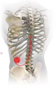
The radiofrequency (RF) magnetic fields induce electric fields throughout the patient and give rise to induced currents and voltages in SCS system components. These can then interact directly with the patient’s tissue. The local RF power deposition, or specific absorption rate (SAR, measured in Watts/kilogram), is different in various tissues of the body. It can concentrate particularly near longer conductive structures, such as leads, due to antenna effects. RF field interactions have the potential for heating to occur at the distal ends of leads near the spinal cord. RF-induced currents can potentially result in device heating and thermal and electrical burns to the patient. It can also lead to device malfunction or failure. The tip of the electrode typically has the highest current flux density and therefore has the greatest potential to generate enough conversion of electrical power into heat so as to damage the dura and underlying spinal cord (Figure 1).
Thermal injury risk increases for temperatures above 430C (for 30 minutes). Significant thermal damage occurs at temperatures above 500C. Literature indicates that lethal cellular dose is 500C for one minute. RF-induced energy at the lead tip due to inappropriate use of the RF body coil to scan the patient’s head has been reported to cause serious neurological injury in a deep brain stimulator patient.
The heat can travel retrograde to the IPG or the IPG itself can heat, resulting in damage to the output circuitry switches, which regulate IPG recovery and capacitor charge balancing. This could allow build-up of voltages on the output capacitors and discharge on initiation of stimulation that can be perceived by the patient as shock sensation. Such IPG damage would require replacement of the IPG.
If one were to undertake revision, I would strongly recommend disconnecting the leads from the IPG and doing on-table testing for assessing any damage to leads before replacing the IPG.
The gradient magnetic field:
The gradient magnetic field is measured in Tesla/second; dB/dt, or as a slew rate in Tesla/meter/second). These are time varying magnetic fluxes that can induce circulating currents in conductive structures. The induced circulating currents (eddy currents) in the metallic case and internal circuitry of an SCS device can result in local heating of the device case leading to the patient feeling a warm/burning sensation in the pocket. They can also induce a magnetic moment that interacts with the MRI static field to exert time-varying/vibratory force or torque on the device.
Less concerning, but also important, are the effects of the medical devices on the operation of the MRI scanner, resulting in poor-quality images due to excessive artifacts, possibly because of the RF currents induced on the surface of the lead. If the IPG or the electrodes are within or near the field of view, some image degradation (distortion, artifact, etc.) is to be expected.
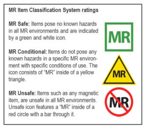
Defining MRI Safety (Figure 2)
I have come across many times when the industry sales and clinical support teams as well as clinicians use MRI ‘Safe’, MRI ‘Compatible’ and MRI ‘Conditional’ terms interchangeably. So what is the difference between these terms?
The US Food and Drug Administration labelling criteria developed by the American Society for Testing and Materials International for portable objects that can be taken into Zone IV of an MRI centre is as follows. The FDA advises SAR level 4 W/kg whole-body average exposure for 15 min and/or Local SAR levels of 8–12 W/kg in any 1g of tissue.
The ‘‘MR safe’’ label is for wholly non-metallic objects, and pose no known hazards in all MR environments. None of the neurostimulation devices on the market are MR Safe.
The ‘‘MR conditional’’ label is for items that have demonstrated to pose no known hazards in a specified MR environment with specified conditions of use.
“MR safe” and “MR compatible” terms were confusing and were often used interchangeably or incorrectly. Hence the term “MR compatible” is removed from current nomenclature.
There are currently two MR conditional SCS systems on the market for whole body scan.
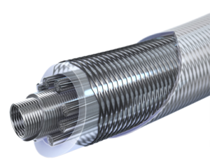
Medtronic has developed the first MR conditional system to allow safe access to MRI scans anywhere in the body. The Medtronic SCS SureScan MRI System includes a family of neurostimulators, Vectris percutaneous and surgical paddle leads. All implanted components of the entire system need to be MR conditional and the appropriate labelling requirements must be followed for a patient to be eligible for a MRI scan anywhere on the body. The Vectris lead design is based on the LZ Octad lead design. The lead has braided body (Figure 3).
This braid acts as an RF shield. It collects the RF energy, keeps it off the conductor wires, and dissipates the energy to the body tissues along the entire length of the lead body. RF energy from the lead can also be dissipated towards the IPG. The IPG has a filtered-feedthrough to shunt high frequency energy to the neurostimulator case where it can dissipate to the subcutaneous tissue around the stimulator. This protects the sensitive electronics, and supports greater heat dissipation across the entire implanted system.

Boston Scientific was next to launch the Precision Montage MRI System and Avista MRI percutaneous lead. There are protective MRI filters embedded into the IPG electronics board that protect the IPG from the strong electromagnetic energy. The percutaneous lead has heat-cancelling technology in the form of layers of the lead which work together to cancel the RF energy that causes heating.
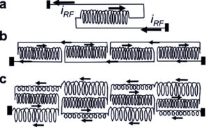
The technology is called billabong current suppression where winding leads with short reversed coiled sections are effective in suppressing induced currents. The coils in each section are wound coaxially to form a triple-layer coil. Each coil is in 6cm sections and is coiled in forward and reversed directions. The outer winding of the first section is connected to the inner winding of the second section (Figure 5).
The induced currents in two closely spaced parallel-connected lead sections are always in the same direction. Current passing through the looped-back coiled section opposes the direction of the induced current between the two ends. (b) Multiple suppression modules of length are assembled from sections with single reversed coils. (c) The straight sections in (b) are also coiled in the triple-coiled billabong. In practice, the coils in each section are wound coaxially to form a triple-layer coil, with the outer winding of the first section connected to the inner winding of the second section, allowing machine winding from a continuous conductor.
The myth is that all neurostimulator patients can have MRI investigations but, the truth is, MRI can be performed only with some devices in a specified MR environment under specified conditions of use.
Ashish Gulve is a consultant in Pain Management at James Cook University Hospital, Middlesbrough, UK


